
Neura Parse hardware / testing in progress
MDR-01
NODERIQ MIRA
Solar-assisted mini drone and docking system
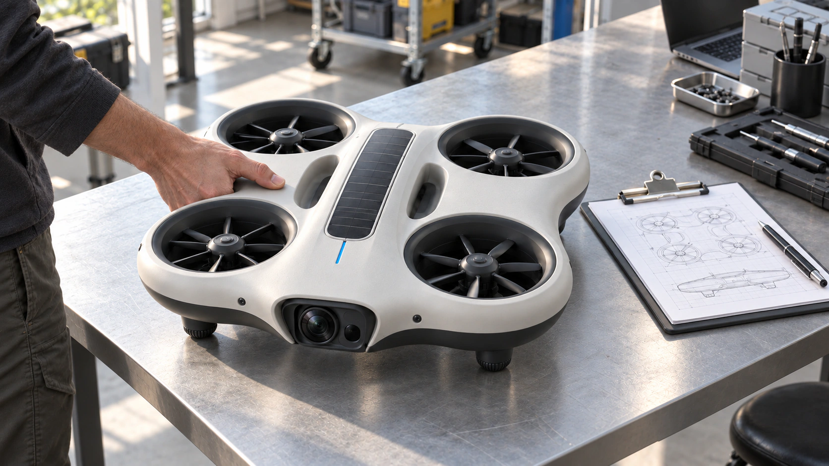
MIRA is our mini autonomous observation drone system in development and testing. Its design explores an integrated protected-fan body, recessed optics and safe carrying grips. Its intended routine observes assigned areas and returns to MIRA Point before the next approved task.
The device and the mission
Regular observation starts with a place to return.
MIRA's design combines a continuous protected-fan frame, recessed handling grips and accessible sensing and power modules. Assigned observation areas, a return point and a reviewable record shape the intended routine.
These visuals explore proposed sensing, return and service arrangements. Final geometry, components and performance remain subject to testing.
Design viewsMDR-01
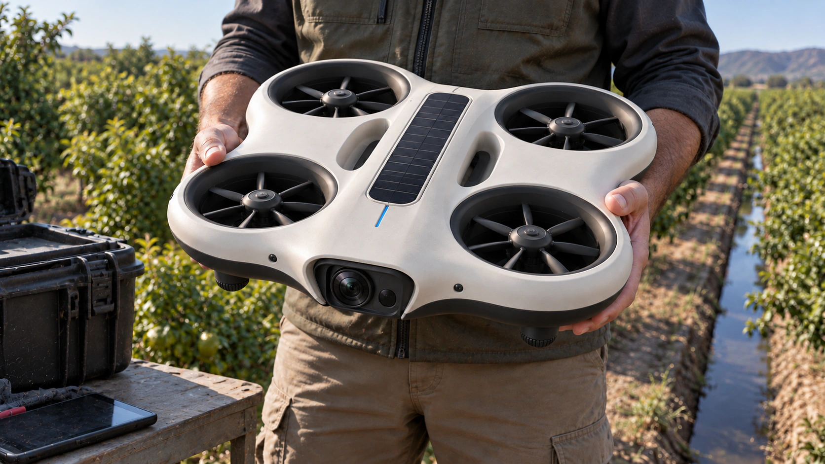
Proposed arrangement / under review
Give the sensor a clear view of the area.
The design puts the observation optics inside a protected front recess, with a view toward the ground. The integrated fan frame and short landing feet are arranged to keep the sensor clear during observation and return.
What needs validation
Evaluate the sensor field of view, vibration, ground clearance and observation quality with the selected payload.
Physical design / R1
Dimensions, access and ground space.
The device, its instruments and its ground station share one dimensional plan. These are proposed design targets for engineering review, not measured product specifications.
Orthographic drawings carry the dimensions. Perspective views show the intended proportions and surroundings. The A3 set includes both devices and both ground layouts; print at 100 percent for the stated scale.
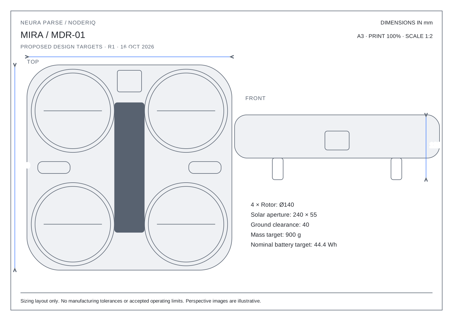
R1 / proposed physical targets
- Overall size
- 380 × 380 × 120 mmLength × width × height, including fins or landing feet.
- Mass allocation
- 900 gComplete device target, including battery and mass allowance.
- Observation module space
- 45 × 40 × 35 mmAllocated component space; sensor resolution and mapping accuracy are not set.
- Battery allocation
- 14.8 V / 3 Ah / 44.4 WhNominal sizing target; chemistry, protection and usable reserve need testing.
- Solar cell aperture
- 240 × 55 mmActive surface allocation; temperature, orientation and shading affect output.
- Rotor layout
- 4 × Ø140 mmIntegrated ducts; guard geometry and contact risk still require testing.
Built around access and observation.
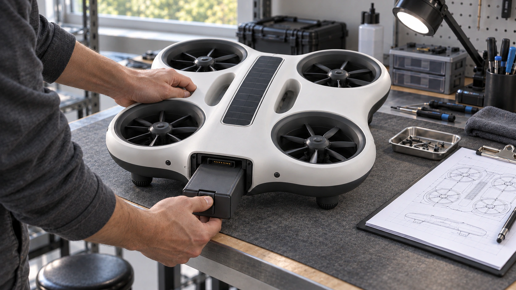
Replaceable duct modules, a lightweight internal frame and accessible fasteners guide the construction. Recessed carrying grips, protected downward optics and rear battery access keep handling separate from the rotor openings. Guarding does not establish touch safety.
Service before release.
Stop propulsion and isolate power before battery or sensor service. The proposed battery space is 100 × 70 × 45 mm, with keyed retention and a protected connection. Latching, thermal behaviour and charging interlocks remain test work.
MIRA Point placement
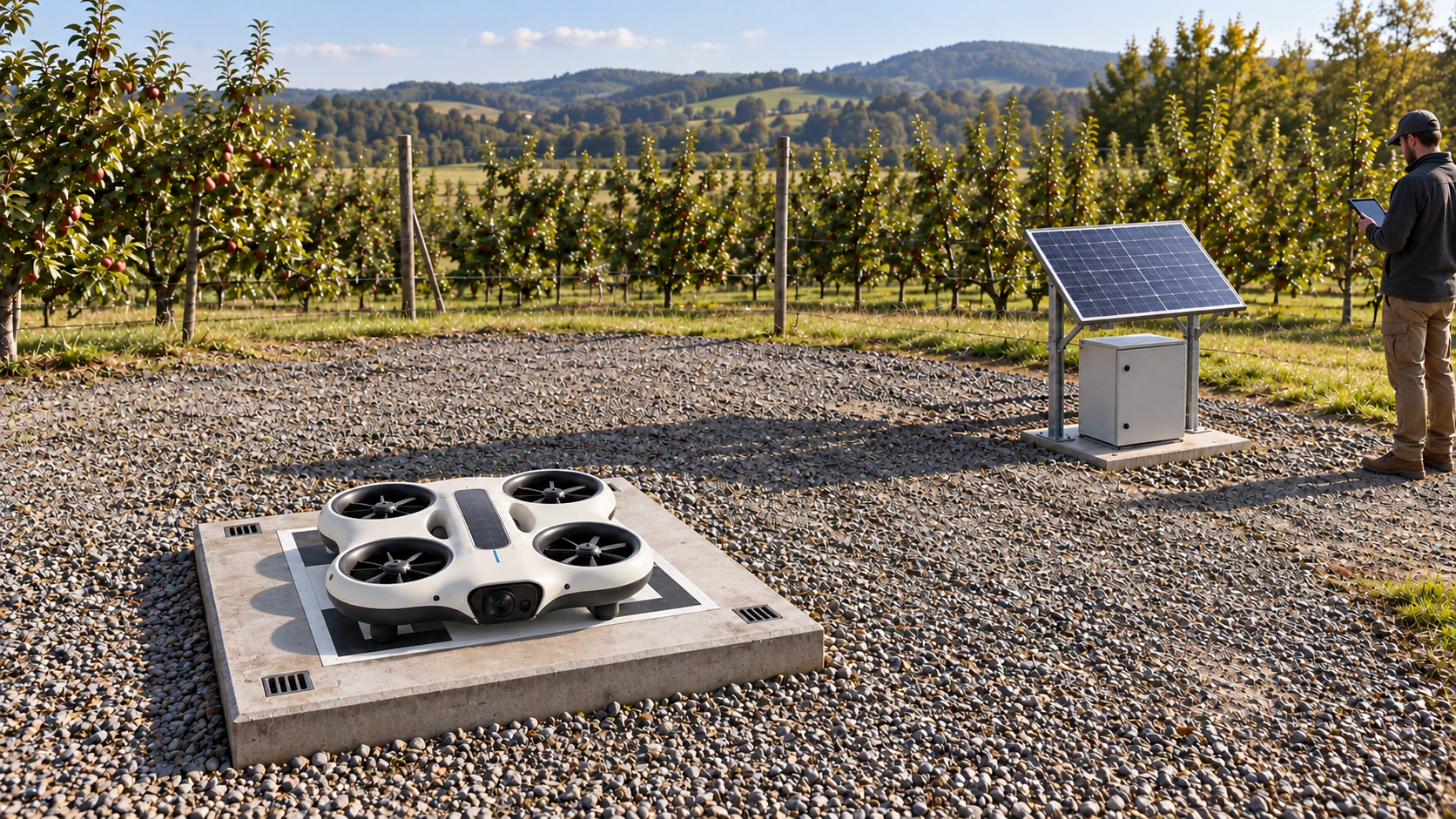
The landing tray, separate solar rack, storage cabinet and covered cable route occupy one planned site. Keep the panel outside the reserved approach space and provide service access without crossing the landing point during operation.
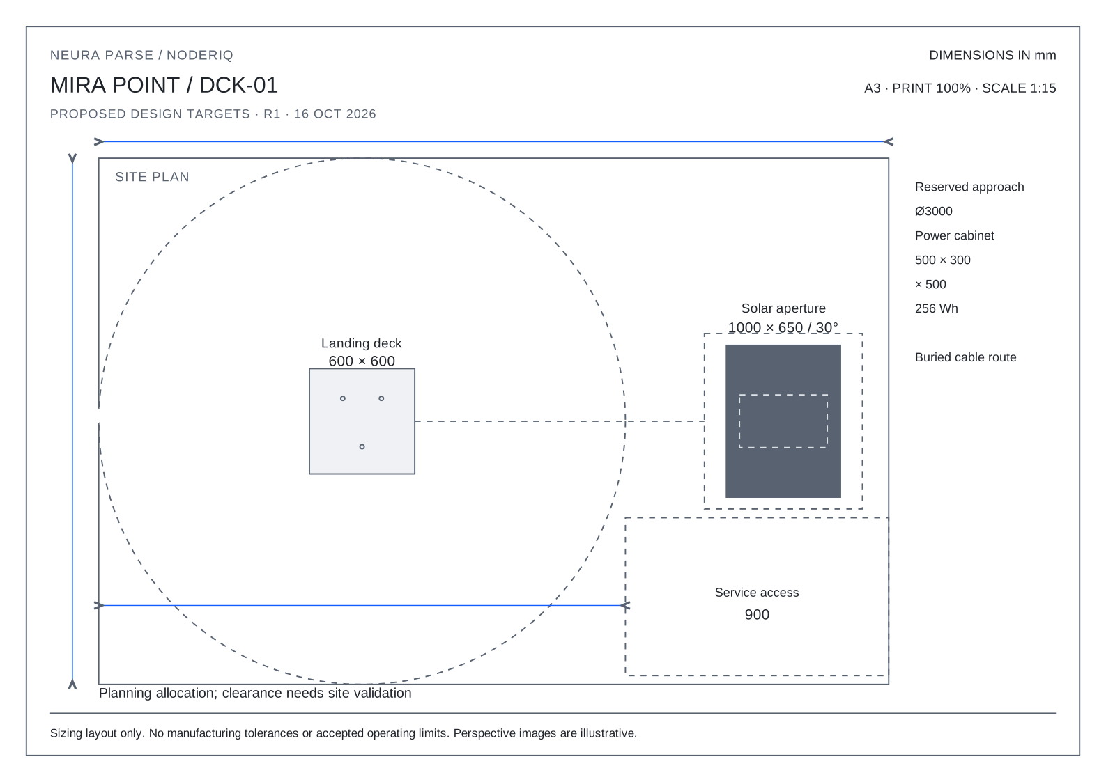
DCK-01 / MIRA Point
- Landing deck
- 600 × 600 × 160 mmFoot-contact seats share the device coordinates; landing alignment is unqualified.
- Solar module allocation
- 1000 × 650 × 30 mmSeparate rack at 30 degrees; panel centre 2400 mm from the landing point.
- Station storage target
- 12.8 V / 20 Ah / 256 WhCharging control, battery protection and weather enclosure need qualification.
- Site allocation
- 4500 × 3000 mmIncludes a reserved 3000 mm approach diameter and 900 mm service access. These are planning allocations, not approved safety clearances.
Mass, energy and the sizing assumptions
Mass budget / proposed allocation
- Frame and ducts
- 220 g
- Motors, rotors and controllers
- 180 g
- Battery
- 260 g
- Flight and communications electronics
- 50 g
- Sensing and navigation
- 70 g
- Solar laminate
- 30 g
- Feet and contact hardware
- 35 g
- Wiring and power conversion
- 25 g
- Unallocated mass allowance
- 30 g
Four 140 mm rotors give an ideal hover-power lower bound of about 68 W at the 900 g mass target and assumed air density of 1.225 kg/m³. The electrical sizing scenario is 180–260 W; real duct, motor, control and sensor losses require bench data. No flight-duration claim follows from the 44.4 Wh nominal battery allocation.
MIRA's 240 × 55 mm solar aperture gives about 2.9 W under the assumed 1000 W/m² and 22 percent efficiency, far below the ideal hover requirement. Solar assistance mainly supports the parked energy strategy. The larger Point aperture gives an ideal 143 W; weather, orientation, storage and charging losses constrain the actual schedule.
These calculations support sizing decisions. They do not establish endurance, weather resistance, operating altitude, mapping accuracy or unattended acceptance.
Inspect the calculation record and sourcesPlanned operating routine / under test
Observe a region. Return to its point.
- 01
Assign a region and point
Set the area, observation interval, mission limits and return point under operator authority.
- 02
Observe the planned area
Collect the selected sensor record with location and capture time within the approved route.
- 03
Return and reconcile
Return to the assigned point; verify the landing and observation record. An unavailable point requires a defined fallback.
- 04
Recharge and review
Check stored energy, device condition and any exceptions before releasing the next scheduled observation.
DCK-01
MIRA Point
Parking, energy and mission readiness
The assigned ground point is part of the MIRA system. Its planned role combines a known return location, solar-assisted charging and a readiness check before another observation. Point placement, landing guidance, storage and charging interfaces are being evaluated with the device.
Weather, an occupied pad, a failed landing or a low battery must change the routine. Recovery behaviour, operator escalation and a safe alternative location need acceptance before unattended operation.
Inspect the return-point viewIntended uses
Start with an observation worth collecting.
Mapping and satellite context
Connect local observations to a geographic reference and, where available, licensed satellite map layers. Capture time, location, source and resolution need to stay visible when comparing observations.
Useful output
A location-linked observation record to compare with the selected map source. Satellite access and mapping accuracy require their own validation.
Environmental observation
Observe defined areas over time: vegetation, water boundaries, agricultural plots or changes in a landscape. Choose and test the sensor and ground-reference method for each question before interpreting a change.
Useful output
A monitoring area, collection schedule and comparison record, with the evidence needed to review a possible change.
Timely field data
Bring useful observations into the mission while they are still relevant. Delivery depends on sensing, processing and connectivity. A lost link or an old frame must remain visible to the operator.
Useful output
Timestamped mission context with source health and explicit treatment of delayed or missing information.
Built towards NODERIQ
From an observation to a decision.
The intended connection brings device observations into NODERIQ mission context. NowFlow provides the workflow and human review layer; NeuraOS provides the edge execution foundation. Hardware integration is part of the testing work.
A map layer, a received message and a completed task are different records. Keep source time, location, freshness, operator authority and the returned outcome connected.
Environmental responsibility
Use energy with a purpose.
Solar power is part of the design direction. Responsible operation also needs a measured account of the complete device, the mission and what happens after use.
- Solar energy and storage
- Evaluate sunlight, battery storage, sensor demand and communications together. MIRA Point adds a larger solar collection surface for parked charging. Night, cloud and battery condition constrain the next mission.
- Observation with a purpose
- Choose the area, collection frequency and sensor for the question. Assess site access, noise, wildlife sensitivity and unnecessary repeat visits as part of each proposed monitoring plan.
- A measurable footprint
- Environmental responsibility includes energy use, materials, service life, maintenance, recovery and end-of-life treatment. Solar assistance is a design choice; a lower overall footprint needs lifecycle evidence.
Current development stage
Hardware tests are ongoing.
Neura Parse is developing and testing these devices for intended use with NODERIQ. The current pages describe the device direction and planned uses. Detailed operating specifications and acceptance results will follow the relevant tests.
The test programme must establish the operating envelope, observation quality, energy budget, connection recovery and return behaviour. Published results will need to support any later coverage, endurance, latency or environmental performance claim. NODERIQ integration and physical operation each require acceptance.
What the device tests must establish
- Assigned monitoring areas
- Define the observation region, revisit schedule, permitted route and sensor task. Autonomous routines are intended to operate within explicit limits and human authority.
- Return and park
- Assign a MIRA Point before release. Approach, landing, charging readiness and an unavailable or occupied point are part of the test scope; docking is not treated as a verified capability yet.
- Energy-aware scheduling
- Combine solar assistance, stored energy and point availability when planning the next task. A small panel does not establish continuous flight; energy reserve and weather affect the schedule.
Technical context and sources
These sources explain buoyancy, observation, landing guidance and solar layout. They provide external engineering context; they do not verify Neura Parse hardware, establish its final design or claim a partnership or adopted software integration.