
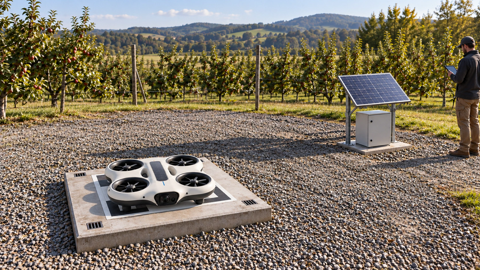
NQ-S50 / Bench evaluation
NODERIQ Sense S50
Precision and inertial sensing
A small acquisition profile combining four simultaneous analog channels with inertial observation for compact instruments and distributed robotic sensing.
EV1 is a defined evaluation specification. Physical board measurements, electrical release and completed system integration are not yet asserted.
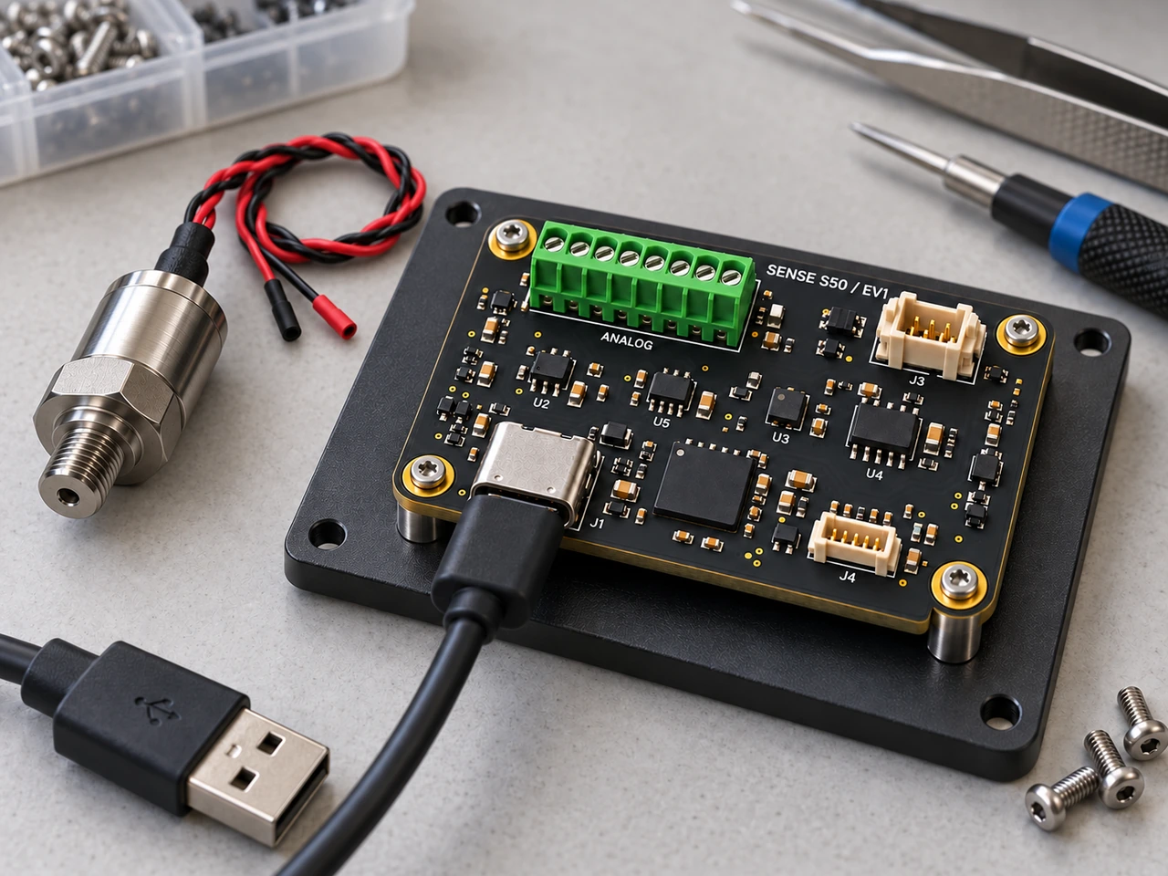
Hardware views
Keep the measurement close to its source.
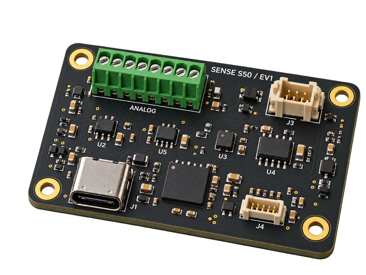
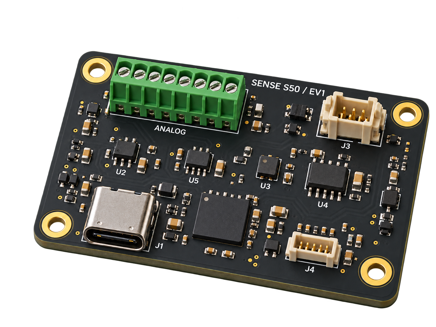
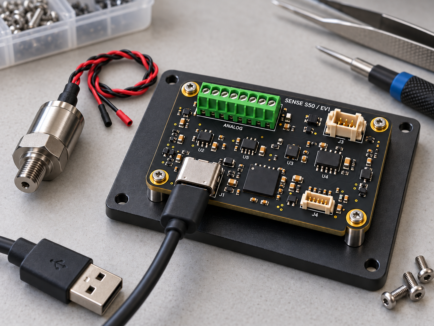
The product image and integration arrangement share the same board identity. Engineering plans and the machine-readable specification own dimensions; generated imagery does not establish an as-built board or a successful test.
Hardware viewsNQ-S50 / EV1
EV1 engineering record
Define the space before the enclosure.
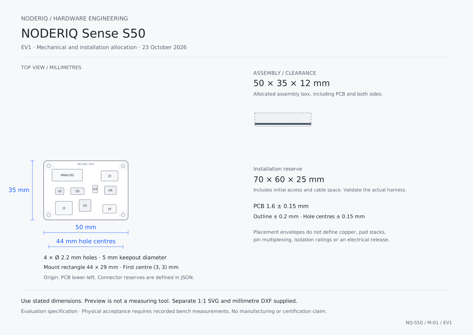
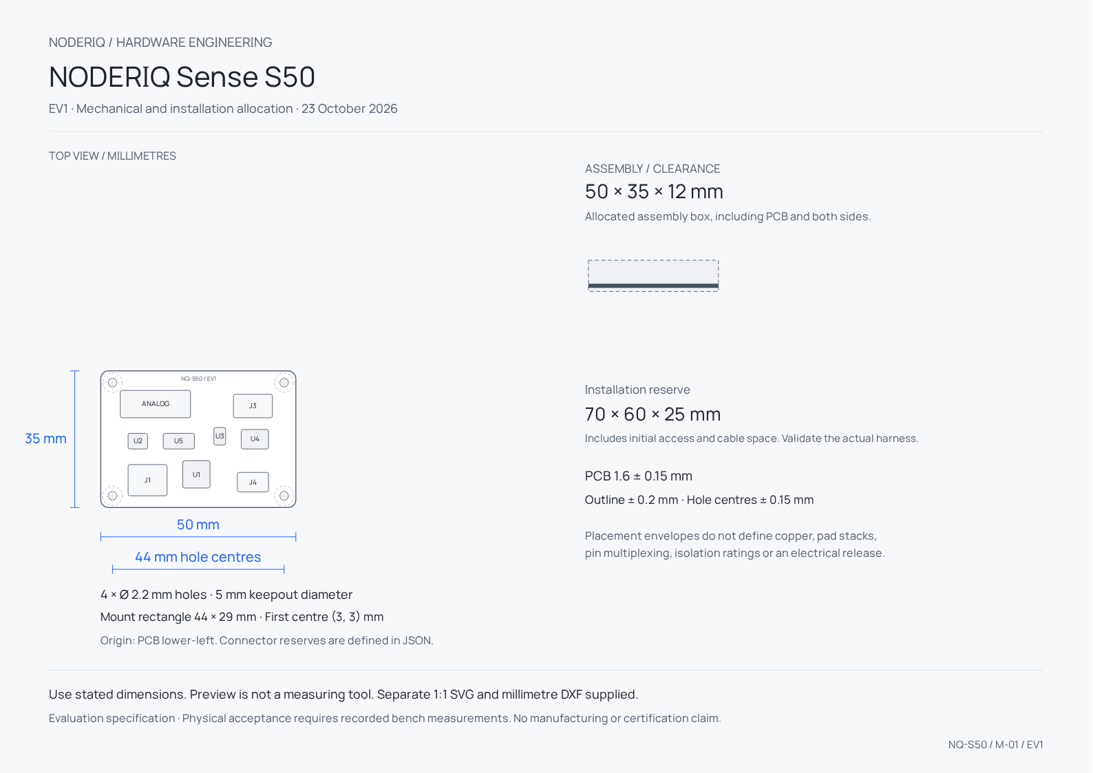
PCB size, assembled height and installation space are separate allocations. Reserve connector access and cable bends, and verify the final fastener and enclosure stack.
Mechanical allocation
- PCB outline
- 50 × 35 mm
- PCB thickness
- 1.6 ± 0.15 mm
- Assembly height
- 12 mmTotal allocated height across both sides, including the PCB.
- Installation reserve
- 70 × 60 × 25 mmInitial access allowance; validate the actual harness and enclosure.
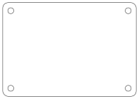
- Mounting holes
- 4 × Ø 2.2 mm
- Hole centres
- (3, 3) · (47, 3) · (47, 32) · (3, 32)Millimetres from the lower-left PCB origin, viewed from the top.
Power and processing allocation
- Processor basis
- STM32U575CGU6 + ADS131M04 + BMI088 basis
- Bench input
- 4.75–5.25 V
- Board power allocation
- 1 WSteady-state screening limit, not a measured consumption result.
- Bench supply
- 5 V / 0.5 AA supply rating does not authorise the same current on every connector.
Interfaces and harnesses
Make every connection explicit.
Connector locations are public placement reserves. They do not substitute for a released pin map, selected mating part or electrical protection review.
- J1USB-CUSB-C envelope
- 5 V input and USB bench data.
- J2ANALOG8-position terminal envelope
- Four low-voltage differential pairs; use the released analog front end and reference source.
- J3CAN4-position locking header
- One non-isolated uplink allocation.
- J4SWD6-position locking header
- 3.3 V debug/service reserve.
Integration roles
Keep intelligence and physical authority connected.
Carry units, source time, calibration reference and sensor orientation with each observation. ADC word length is not measurement accuracy.
Distributed sensing node
Mount close to low-voltage transducers, separated from motor wiring and the compute cooler. Keep shield and reference routing explicit.
Instrumented end effector
Fix the sensor orientation and strain relief so motion measurements refer to a known physical frame.
Hardware observations can support NODERIQ mission context. NowFlow supplies the workflow role and NeuraOS the edge foundation; a board illustration does not establish that those layers are integrated or authorised to control a machine.
Product documents
A complete record for the evaluation bench.
Use the product guide, dimensioned plans, original images and blank measurement record together. Technical downloads retain their English source language and stated units.
Bench qualification
Measure the complete configuration.
Four-channel acquisition at a 4 kSPS evaluation setting, gain 1, a traceable 0.5 V differential stimulus within the approved common-mode range, and a stationary IMU fixture.
The analog front end must be electrically released for its sensors before power-up. No direct mains, 24 V analog input, calibrated accuracy, vibration rating or environmental sealing is implied.
Component sources and current limits
- STMicroelectronics / STM32U575CG (English)
S50 basis: 7 × 7 mm UFQFPN48 option, USB full speed and CAN FD; actual pin multiplexing must be resolved in the electrical release.
- Texas Instruments / ADS131M04 simultaneous ADC (English)
Four simultaneous 24-bit channels. EV1 tests use 4 kSPS rather than asserting the component maximum as board throughput or accuracy.
- Bosch Sensortec / BMI088 inertial sensor (English)
3 × 4.5 × 0.95 mm inertial package; vibration and temperature behavior must be measured in the final mounting arrangement.
- JST / GH locking wire-to-board family (English)
1.25 mm connector-pitch reference. Public connector envelopes are reserved integration space, not an approved land pattern.