
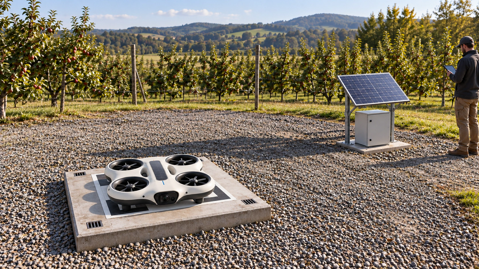
NQ-V80 / Bench evaluation
NODERIQ Vision V80
Camera-local intelligence
A low-profile camera-processing board architecture for inspection heads, fixed observation nodes and lightweight robotic perception modules.
EV1 is a defined evaluation specification. Physical board measurements, electrical release and completed system integration are not yet asserted.
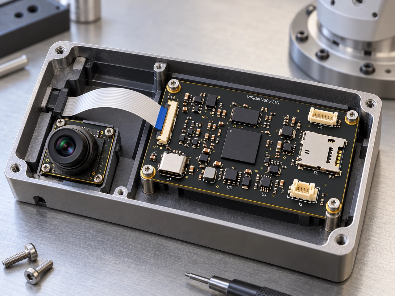
Hardware views
Process the view near the lens.
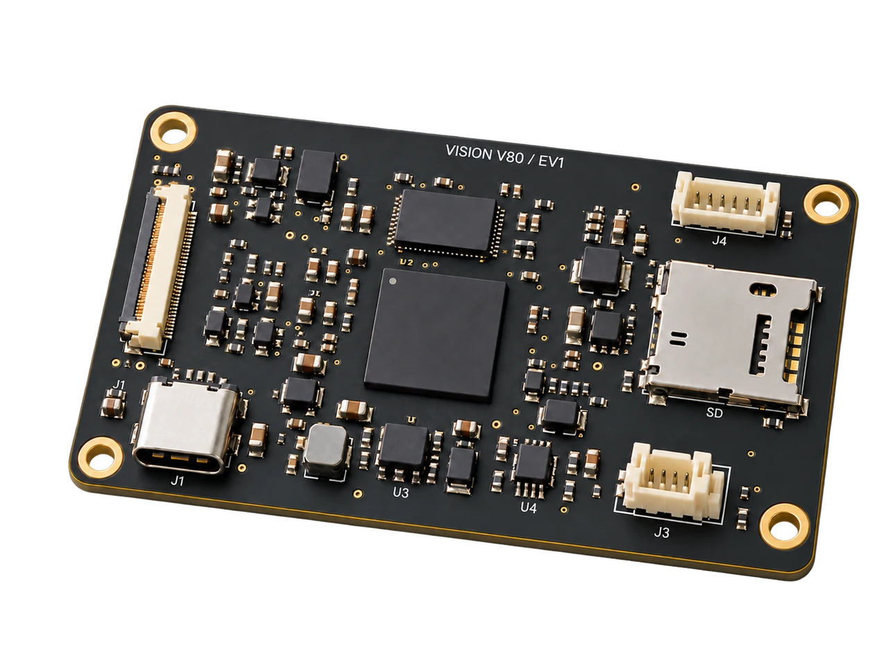
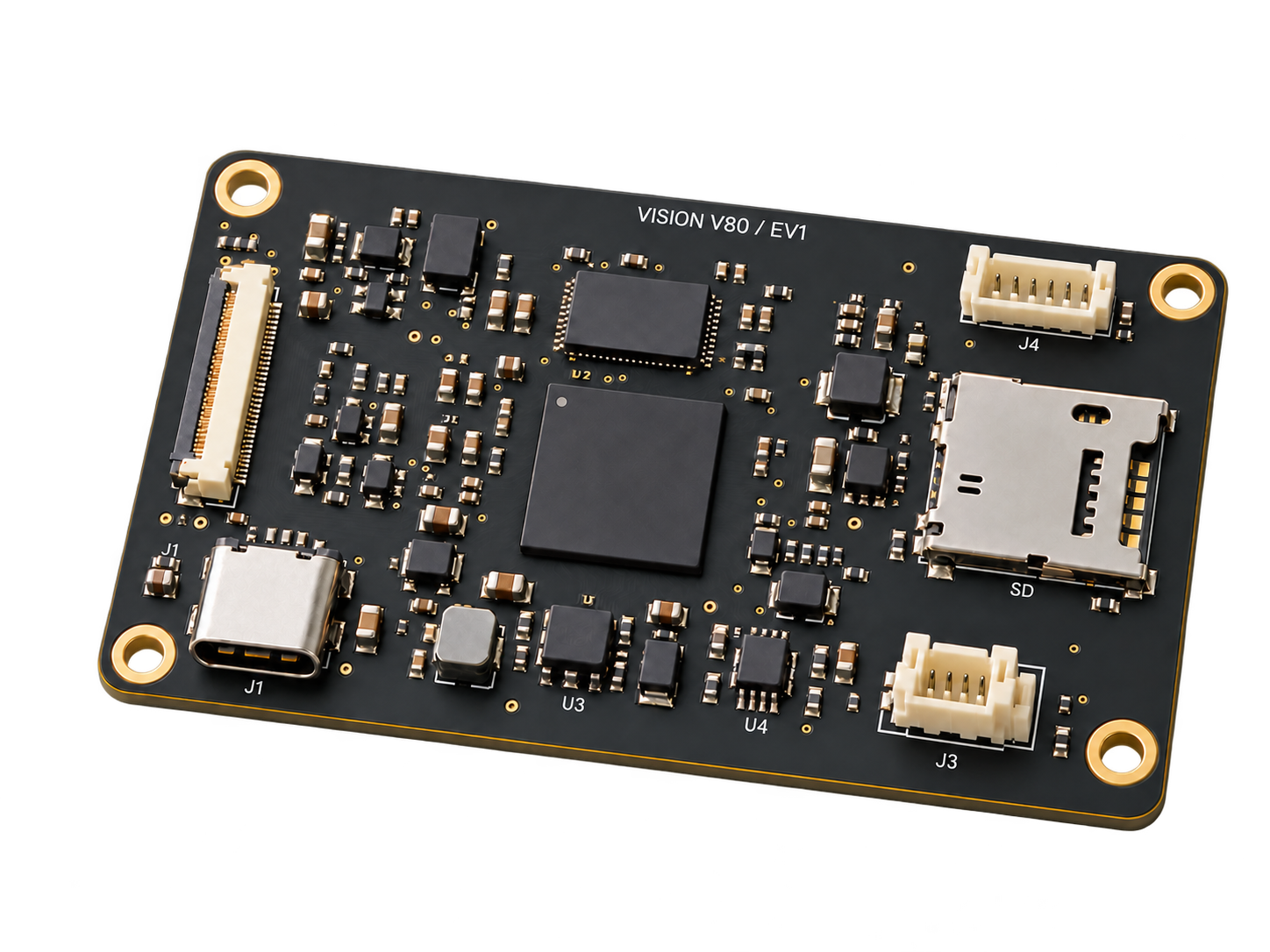
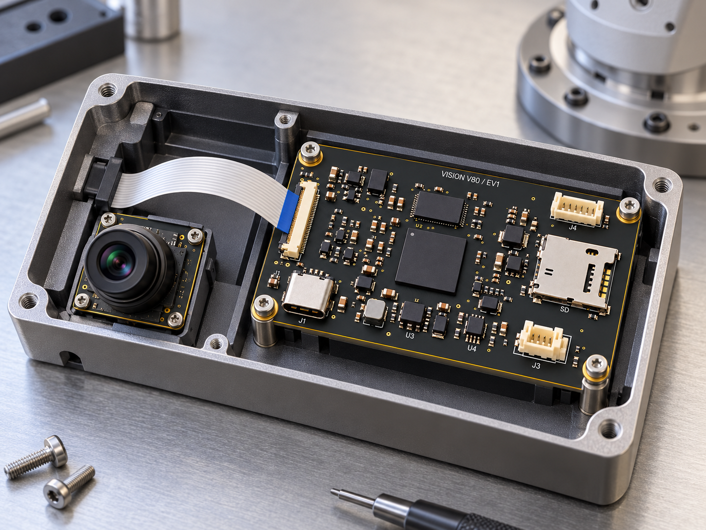
The product image and integration arrangement share the same board identity. Engineering plans and the machine-readable specification own dimensions; generated imagery does not establish an as-built board or a successful test.
Hardware viewsNQ-V80 / EV1
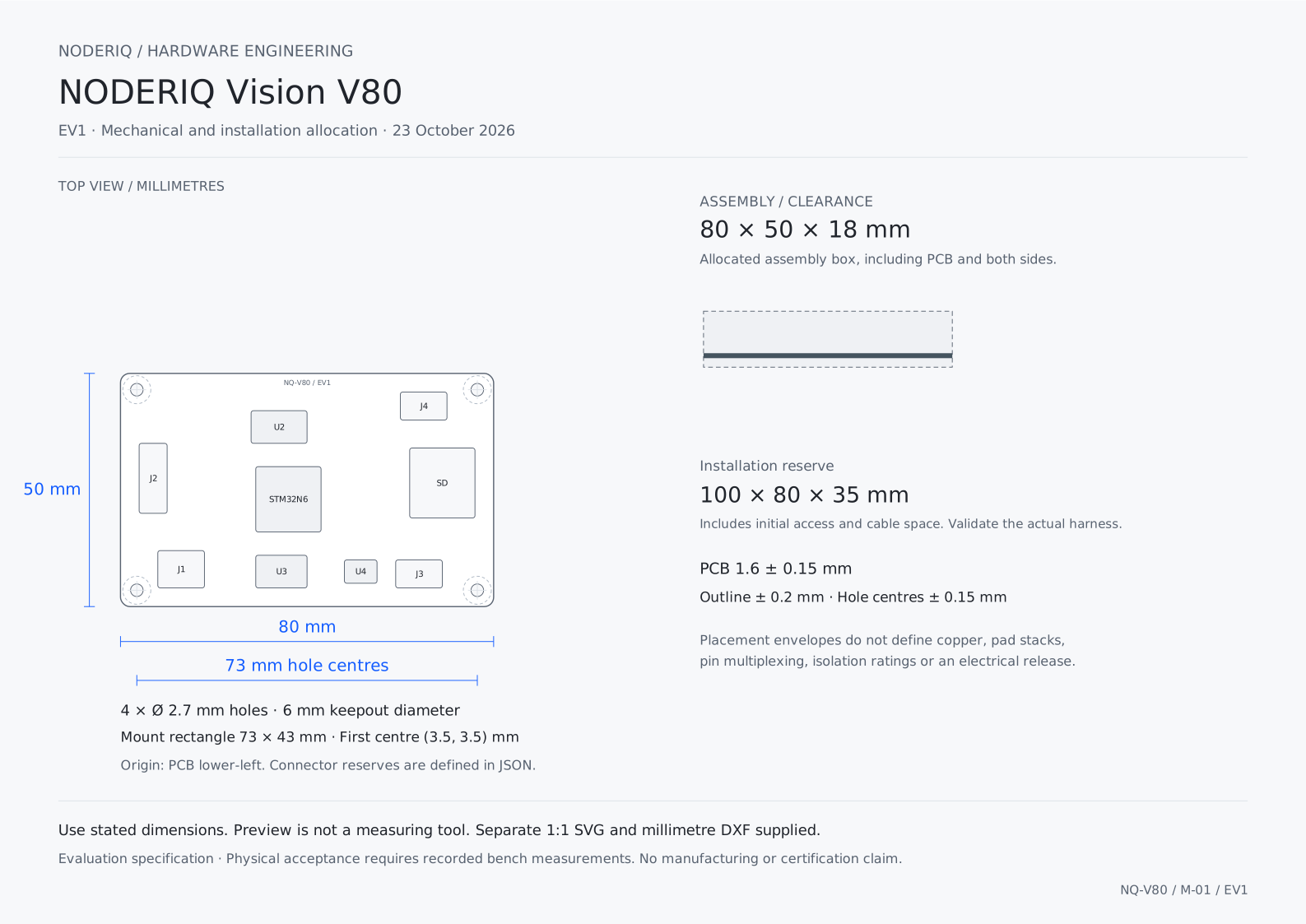
EV1 engineering record
Define the space before the enclosure.
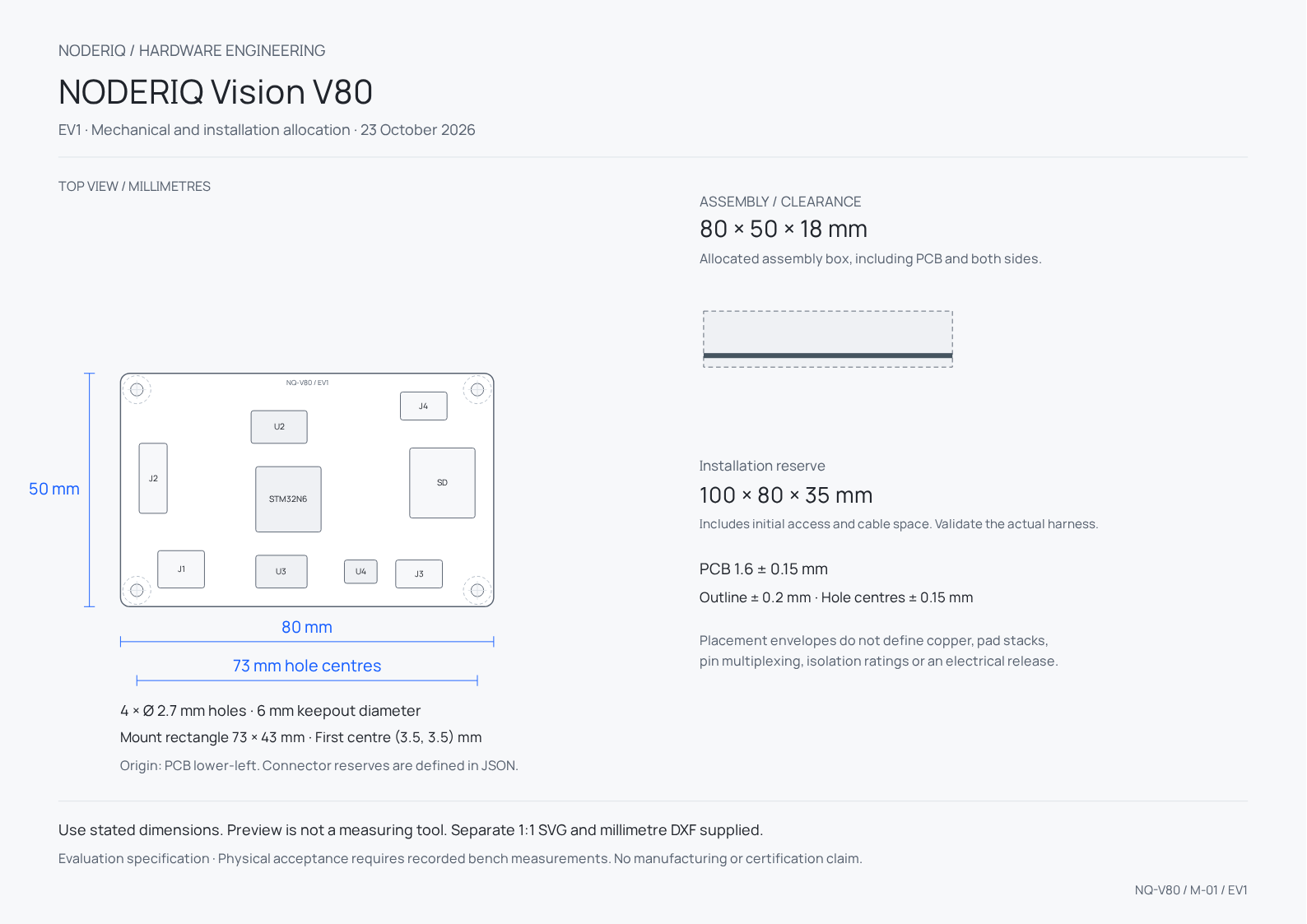
PCB size, assembled height and installation space are separate allocations. Reserve connector access and cable bends, and verify the final fastener and enclosure stack.
Mechanical allocation
- PCB outline
- 80 × 50 mm
- PCB thickness
- 1.6 ± 0.15 mm
- Assembly height
- 18 mmTotal allocated height across both sides, including the PCB.
- Installation reserve
- 100 × 80 × 35 mmInitial access allowance; validate the actual harness and enclosure.
- Mounting holes
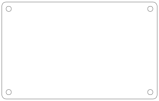
- 4 × Ø 2.7 mm
- Hole centres
- (3.5, 3.5) · (76.5, 3.5) · (76.5, 46.5) · (3.5, 46.5)Millimetres from the lower-left PCB origin, viewed from the top.
Power and processing allocation
- Processor basis
- STM32N657X0H3Q basis
- Bench input
- 4.75–5.25 V
- Board power allocation
- 10 WSteady-state screening limit, not a measured consumption result.
- Bench supply
- 5 V / 3 AA supply rating does not authorise the same current on every connector.
Interfaces and harnesses
Make every connection explicit.
Connector locations are public placement reserves. They do not substitute for a released pin map, selected mating part or electrical protection review.
- J1USB-CUSB-C envelope
- 5 V input and USB data; no higher-voltage USB PD input.
- J2CAM22-position FFC envelope
- Two-lane CSI camera assembly, with a qualified sensor/ribbon combination.
- J3CAN4-position locking header
- Supervised observation link to an existing controller.
- J4UART6-position locking header
- 3.3 V service signals; no RS-232 voltages.
- J5SDmicroSD envelope
- Removable local recording reserve.
Integration roles
Keep intelligence and physical authority connected.
The local camera pipeline returns observations. An inference output alone cannot authorise machine motion or bypass the host review path.
Robotic inspection head
Keep the camera ribbon short and strain relieved. Maintain an accessible optical path and a separate machine stop circuit.
Fixed vision node
Place a small camera module near the observed process and return timestamped observations to the host.
Hardware observations can support NODERIQ mission context. NowFlow supplies the workflow role and NeuraOS the edge foundation; a board illustration does not establish that those layers are integrated or authorised to control a machine.
Product documents
A complete record for the evaluation bench.
Use the product guide, dimensioned plans, original images and blank measurement record together. Technical downloads retain their English source language and stated units.
Bench qualification
Measure the complete configuration.
A fixed 640 × 480 camera capture fixture; record sensor, pixel format, exposure and compiled firmware. Evaluate any neural model in a separate named workload.
The STM32N6 source establishes component capabilities. Camera compatibility, external memory, firmware, model accuracy and board throughput require the named bench fixture; the chip maximum is not an achieved V80 result.
Component sources and current limits
- STMicroelectronics / STM32N657X0 (English)
V80 basis: 14 × 14 mm VFBGA264 package, Cortex-M55, on-chip SRAM, camera pipeline and NPU. Board performance requires workload measurements.
- JST / GH locking wire-to-board family (English)
1.25 mm connector-pitch reference. Public connector envelopes are reserved integration space, not an approved land pattern.